DICASO Project
This page is documenting a wip protoype for a recording device to use in emergency cases, to record the owner's sound environment. It could be use in several scenarios including arrassment in order to record a sound proof of violences towards someone or the voice of the agressor.
This research project is carried by Jean-Daniel Fekete, Petra Isenberg, Romain Di Vozzo, from Inria laboratories, and myself, student in the Fablab Digiscope.
Process
- Microphone amplifier
- Converting analog signal to digital signal
- Storing data on a SD card
Ressources
Pre-amplification + audio processing with Arduino :
Saving data to SD card with Arduino :
- https://www.instructables.com/Arduino-Mega-Audio-File-logging/
- https://maker.pro/arduino/tutorial/how-to-make-an-arduino-sd-card-data-logger-for-temperature-sensor-data
1. LM386 Microphone Amplifier
Ressources
- http://www.learningaboutelectronics.com/Articles/Microphone-amplifier-circuit.php
- https://lowvoltage.wordpress.com/2011/05/15/lm386-mic-amp/


2. Converting analog signal to digital signal
Ressources
- https://www.instructables.com/Arduino-Audio-Input/
- http://www.gecif.net/qcm/information/table_de_conversion.pdf
The R2R resistor ladder Digital to Analog circuit

The R2R resistor ladder DAC is a summing circuit which takes incoming digital bits, weights them and sums them to produce a voltage between 0V and 5V. This resistor ladder is an 8-bit DAC, therefore it can produce 256(2^8) voltage levels between 0 and 5V.
| Quantity | Component |
|---|---|
| 7 | 10k resistors |
| 9 | 20k resistors |
| or | - |
| 16 | 10k resistors |
| 10~ | Jump wires |

As shown on the image below, the resistor ladder is wired from 0 to 7 on the digital pins.

Code & Oscilloscope outputs
Testing the resistor ladder with digitalWrite()
void setup(){
  for (int i=0;i<8;i++){    //set digital pins 0-7 as outputs
    pinMode(i,OUTPUT);
  }

  pinMode(A0,INPUT);
  Serial.begin(9600);
  while (! Serial);
  Serial.println("Digital to Analog Converter");
}

void loop(){
  digitalWrite(0, HIGH); // 1
  digitalWrite(1, HIGH);  // 1
  digitalWrite(2, LOW);  // 0
  digitalWrite(3, LOW);  // 0
  digitalWrite(4, HIGH); // 1
  digitalWrite(5, HIGH); // 1
  digitalWrite(6, LOW);  // 0
  digitalWrite(7, LOW); // 0 > MSB
}
- 00000000 = 0 = 0V

- 11111111 = 255 = 5V

- 01111111 = 127 = 2.5V
- 00110011 = 51 = 1V
- Using the Arbitrary Function Generator to generate waveforms

By modifying the offset of the incoming signal we can avoid clipping. In this case modifying the offset to 1.30V solved this problem.

- PORTD : adressing the port directly
The previous code is using the digitalWrite(), in the next codes, available on Amanda Ghassaei's instructables, another method allows us to address the port directly. (https://www.arduino.cc/en/Reference/PortManipulation)
"On the Arduino, digital pins 0-7 are all on port d of the Atmel328 chip. The PORTD command lets us tells pins 0-7 to go HIGH or LOW in one line (instead of having to use digitalWrite() eight times). Not only is this easier to code, it's much faster for the Arduino to process and it causes the pins to all change simultaneously instead of one by one (you can only talk to one pin at a time with digitalWrite()). Since port d has eight pins on it (digital pins 0-7) we can send it one of 2^8 = 256 possible values (0-255) to control the pins." source : Amanda Ghassaei - https://www.instructables.com/Arduino-Audio-Output/
Simple Audio In with output to 8 bit DAC
//Simple Audio In w output to 8 bit DAC
//by Amanda Ghassaei
//https://www.instructables.com/id/Arduino-Audio-Input/
//Sept 2012

/*
 * This program is free software; you can redistribute it and/or modify
 * it under the terms of the GNU General Public License as published by
 * the Free Software Foundation; either version 3 of the License, or
 * (at your option) any later version.
 *
*/

int incomingAudio;

void setup(){
  for (byte i=0;i<8;i++){
    pinMode(i,OUTPUT);//set digital pins 0-7 as outputs (DAC)
  }
}

void loop(){
  incomingAudio = analogRead(A0);//read voltage at A0
  incomingAudio = (incomingAudio+1)/4 - 1;//scale from 10 bit (0-1023) to 8 bit (0-255)
  if (incomingAudio<0){//deal with negative numbers
    incomingAudio = 0;
  }
  PORTD = incomingAudio;
}


Audio out with 38.5kHz sampling rate and DAC output
//Audio out with 38.5kHz sampling rate and DAC output
//by Amanda Ghassaei
//https://www.instructables.com/id/Arduino-Audio-Input/
//Sept 2012

/*
 * This program is free software; you can redistribute it and/or modify
 * it under the terms of the GNU General Public License as published by
 * the Free Software Foundation; either version 3 of the License, or
 * (at your option) any later version.
 *
*/

void setup(){

  for (byte i=0;i<8;i++){
    pinMode(i,OUTPUT);
  }

  //set up continuous sampling of analog pin 0

  //clear ADCSRA and ADCSRB registers
  ADCSRA = 0;
  ADCSRB = 0;

  ADMUX |= (1 << REFS0); //set reference voltage
  ADMUX |= (1 << ADLAR); //left align the ADC value- so we can read highest 8 bits from ADCH register only

  ADCSRA |= (1 << ADPS2) | (1 << ADPS0); //set ADC clock with 32 prescaler- 16mHz/32=500kHz
  ADCSRA |= (1 << ADATE); //enabble auto trigger
  ADCSRA |= (1 << ADEN); //enable ADC
  ADCSRA |= (1 << ADSC); //start ADC measurements

  //if you want to add other things to setup(), do it here

}

void loop(){
  PORTD = ADCH;//send 8 bit value from analog pin 0 to DAC
}

Audio Out with 38.5kHz sampling rate and interrupts
//Audio out with 38.5kHz sampling rate and interrupts
//by Amanda Ghassaei
//https://www.instructables.com/id/Arduino-Audio-Input/
//Sept 2012

/*
 * This program is free software; you can redistribute it and/or modify
 * it under the terms of the GNU General Public License as published by
 * the Free Software Foundation; either version 3 of the License, or
 * (at your option) any later version.
 *
*/

int incomingAudio;

void setup(){
    for (byte i=0;i<8;i++){
    pinMode(i,OUTPUT);//set digital pins 0-7 as outputs (DAC)
  }

  cli();//disable interrupts

  //set up continuous sampling of analog pin 0

  //clear ADCSRA and ADCSRB registers
  ADCSRA = 0;
  ADCSRB = 0;

  ADMUX |= (1 << REFS0); //set reference voltage
  ADMUX |= (1 << ADLAR); //left align the ADC value- so we can read highest 8 bits from ADCH register only

  ADCSRA |= (1 << ADPS2) | (1 << ADPS0); //set ADC clock with 32 prescaler- 16mHz/32=500kHz
  ADCSRA |= (1 << ADATE); //enabble auto trigger
  ADCSRA |= (1 << ADIE); //enable interrupts when measurement complete
  ADCSRA |= (1 << ADEN); //enable ADC
  ADCSRA |= (1 << ADSC); //start ADC measurements

  sei();//enable interrupts

  //if you want to add other things to setup(), do it here

}

ISR(ADC_vect) {//when new ADC value ready
  incomingAudio = ADCH;//update the variable incomingAudio with new value from A0 (between 0 and 255)
}

void loop(){
  PORTD = incomingAudio;
}

3. Storing data
A. Storing audio data with Audacity
This part will show how to store audio data from the LM386 microcophone amplifier circuit. To do so we need to add a 3.5mm Audio jack to our circuit and plug it in to the computer. It may be necessary to check the parameters so the 3.5 mm Jack appears to a Microphone for the computer, and not to a headphone.
We also need to download Audacity to record what the microphone is recording. The software is free and opensource, it is available herer : https://audacity.fr/.
We'll use the Analog Read Serial sketch from the Arduino's examples. This way we can see what is capting our microphone.

/*
  AnalogReadSerial

  Reads an analog input on pin 0, prints the result to the Serial Monitor.
  Graphical representation is available using Serial Plotter (Tools > Serial Plotter menu).
  Attach the center pin of a potentiometer to pin A0, and the outside pins to +5V and ground.

  This example code is in the public domain.

  http://www.arduino.cc/en/Tutorial/AnalogReadSerial
*/

// the setup routine runs once when you press reset:
void setup() {
  // initialize serial communication at 9600 bits per second:
  Serial.begin(9600);
}

// the loop routine runs over and over again forever:
void loop() {
  // read the input on analog pin 0:
  int sensorValue = analogRead(A0);
  // print out the value you read:
  Serial.println(sensorValue);
  delay(1);        // delay in between reads for stability
}
By using the Serial Plotter we can see how the audio signal is behaving when there's sound. The tapping sound in the video is recorded by the computer, not the circuit.
We need to select our audio source, then when the sketch is on, we can record the sound by clicking on the red button under the "generate" menu in the Audacity's interface.

And this is the audio recorded from the mic amplifier circuit. This is very noisy. This part is focused on how to "export" audio data from the arduino, a filter will be needed to get workable audio.
I HIGHLY RECOMMEND YOU TO PUT THE SOUND DOWN before playing the audio. (Next time I'll use a music, sorry.)
B. Storing data on the Arduino's EEPROM
C. Storing data on a SD card
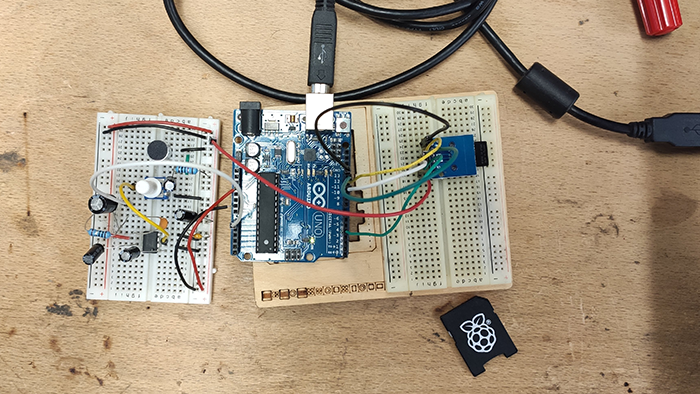
First thing first, we have to wire the SD Card module, this link provided by Jonah, has been a relevant help for this part : https://learn.adafruit.com/adafruit-micro-sd-breakout-board-card-tutorial/arduino-library
/*
SD card test
This example shows how use the utility libraries on which the'
SD library is based in order to get info about your SD card.
Very useful for testing a card when you're not sure whether its working or not.
The circuit:
SD card attached to SPI bus as follows:
** MOSI - pin 11 on Arduino Uno/Duemilanove/Diecimila
** MISO - pin 12 on Arduino Uno/Duemilanove/Diecimila
** CLK - pin 13 on Arduino Uno/Duemilanove/Diecimila
** CS - depends on your SD card shield or module.
Pin 4 used here for consistency with other Arduino examples
created 28 Mar 2011
by Limor Fried
modified 9 Apr 2012
by Tom Igoe
*/
// include the SD library:
#include <SPI.h>
#include <SD.h>
// set up variables using the SD utility library functions:
Sd2Card card;
SdVolume volume;
SdFile root;
// change this to match your SD shield or module;
// Arduino Ethernet shield: pin 4
// Adafruit SD shields and modules: pin 10
// Sparkfun SD shield: pin 8
// MKRZero SD: SDCARD_SS_PIN
const int chipSelect = 4;
void setup() {
// Open serial communications and wait for port to open:
Serial.begin(9600);
while (!Serial) {
; // wait for serial port to connect. Needed for native USB port only
}
Serial.print("\nInitializing SD card...");
// we'll use the initialization code from the utility libraries
// since we're just testing if the card is working!
if (!card.init(SPI_HALF_SPEED, chipSelect)) {
Serial.println("initialization failed. Things to check:");
Serial.println("* is a card inserted?");
Serial.println("* is your wiring correct?");
Serial.println("* did you change the chipSelect pin to match your shield or module?");
while (1);
} else {
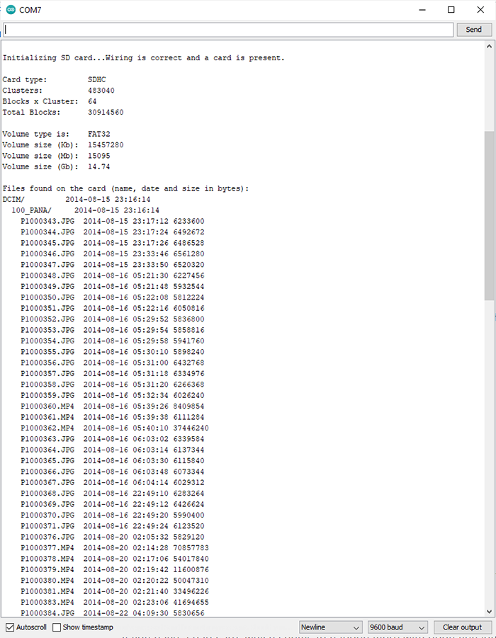
Serial.println("Wiring is correct and a card is present.");
}
// print the type of card
Serial.println();
Serial.print("Card type: ");
switch (card.type()) {
case SD_CARD_TYPE_SD1:
Serial.println("SD1");
break;
case SD_CARD_TYPE_SD2:
Serial.println("SD2");
break;
case SD_CARD_TYPE_SDHC:
Serial.println("SDHC");
break;
default:
Serial.println("Unknown");
}
// Now we will try to open the 'volume'/'partition' - it should be FAT16 or FAT32
if (!volume.init(card)) {
Serial.println("Could not find FAT16/FAT32 partition.\nMake sure you've formatted the card");
while (1);
}
Serial.print("Clusters: ");
Serial.println(volume.clusterCount());
Serial.print("Blocks x Cluster: ");
Serial.println(volume.blocksPerCluster());
Serial.print("Total Blocks: ");
Serial.println(volume.blocksPerCluster() * volume.clusterCount());
Serial.println();
// print the type and size of the first FAT-type volume
uint32_t volumesize;
Serial.print("Volume type is: FAT");
Serial.println(volume.fatType(), DEC);
volumesize = volume.blocksPerCluster(); // clusters are collections of blocks
volumesize *= volume.clusterCount(); // we'll have a lot of clusters
volumesize /= 2; // SD card blocks are always 512 bytes (2 blocks are 1KB)
Serial.print("Volume size (Kb): ");
Serial.println(volumesize);
Serial.print("Volume size (Mb): ");
volumesize /= 1024;
Serial.println(volumesize);
Serial.print("Volume size (Gb): ");
Serial.println((float)volumesize / 1024.0);
Serial.println("\nFiles found on the card (name, date and size in bytes): ");
root.openRoot(volume);
// list all files in the card with date and size
root.ls(LS_R | LS_DATE | LS_SIZE);
}
void loop(void) {
}
/*
SD card read/write
This example shows how to read and write data to and from an SD card file
The circuit:
SD card attached to SPI bus as follows:
** MOSI - pin 11
** MISO - pin 12
** CLK - pin 13
** CS - pin 4 (for MKRZero SD: SDCARD_SS_PIN)
created Nov 2010
by David A. Mellis
modified 9 Apr 2012
by Tom Igoe
This example code is in the public domain.
*/
#include <SPI.h>
#include <SD.h>
File myFile;
void setup() {
// Open serial communications and wait for port to open:
Serial.begin(9600);
while (!Serial) {
; // wait for serial port to connect. Needed for native USB port only
}
Serial.print("Initializing SD card...");
if (!SD.begin(4)) {
Serial.println("initialization failed!");
while (1);
}
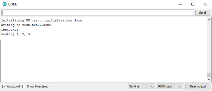
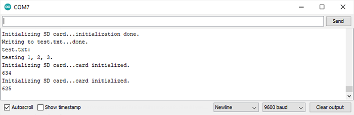
Serial.println("initialization done.");
// open the file. note that only one file can be open at a time,
// so you have to close this one before opening another.
myFile = SD.open("test.txt", FILE_WRITE);
// if the file opened okay, write to it:
if (myFile) {
Serial.print("Writing to test.txt...");
myFile.println("testing 1, 2, 3.");
// close the file:
myFile.close();
Serial.println("done.");
} else {
// if the file didn't open, print an error:
Serial.println("error opening test.txt");
}
// re-open the file for reading:
myFile = SD.open("test.txt");
if (myFile) {
Serial.println("test.txt:");
// read from the file until there's nothing else in it:
while (myFile.available()) {
Serial.write(myFile.read());
}
// close the file:
myFile.close();
} else {
// if the file didn't open, print an error:
Serial.println("error opening test.txt");
}
}
void loop() {
// nothing happens after setup
}
/*
SD card datalogger
This example shows how to log data from three analog sensors
to an SD card using the SD library.
The circuit:
analog sensors on analog ins 0, 1, and 2
SD card attached to SPI bus as follows:
** MOSI - pin 11
** MISO - pin 12
** CLK - pin 13
** CS - pin 4 (for MKRZero SD: SDCARD_SS_PIN)
created 24 Nov 2010
modified 9 Apr 2012
by Tom Igoe
This example code is in the public domain.
*/
#include <SPI.h>
#include <SD.h>
const int chipSelect = 4;
void setup() {
// Open serial communications and wait for port to open:
Serial.begin(9600);
while (!Serial) {
; // wait for serial port to connect. Needed for native USB port only
}
Serial.print("Initializing SD card...");
// see if the card is present and can be initialized:
if (!SD.begin(chipSelect)) {
Serial.println("Card failed, or not present");
// don't do anything more:
while (1);
}
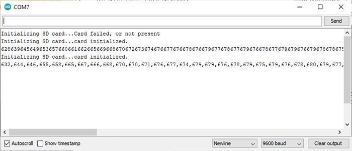
Serial.println("card initialized.");
}
void loop() {
// make a string for assembling the data to log:
String dataString = "";
// read three sensors and append to the string:
for (int analogPin = 0; analogPin < 3; analogPin++) {
int sensor = analogRead(analogPin);
dataString += String(sensor);
if (analogPin < 2) {
dataString += ",";
}
}
// open the file. note that only one file can be open at a time,
// so you have to close this one before opening another.
File dataFile = SD.open("datalog.txt", FILE_WRITE);
// if the file is available, write to it:
if (dataFile) {
dataFile.println(dataString);
dataFile.close();
// print to the serial port too:
Serial.println(dataString);
}
// if the file isn't open, pop up an error:
else {
Serial.println("error opening datalog.txt");
}
}
/*
  SD card datalogger

  This example shows how to log data from three analog sensors
  to an SD card using the SD library.

  The circuit:
   analog sensors on analog ins 0, 1, and 2
   SD card attached to SPI bus as follows:
 ** MOSI - pin 11
 ** MISO - pin 12
 ** CLK - pin 13
 ** CS - pin 4 (for MKRZero SD: SDCARD_SS_PIN)

  created  24 Nov 2010
  modified 9 Apr 2012
  by Tom Igoe

  This example code is in the public domain.

*/

#include <SPI.h>
#include <SD.h>

const int chipSelect = 4;

void setup() {
  // Open serial communications and wait for port to open:
  Serial.begin(9600);
  while (!Serial) {
    ; // wait for serial port to connect. Needed for native USB port only
  }


  Serial.print("Initializing SD card...");

  // see if the card is present and can be initialized:
  if (!SD.begin(chipSelect)) {
    Serial.println("Card failed, or not present");
    // don't do anything more:
    while (1);
  }
  Serial.println("card initialized.");

    // make a string for assembling the data to log:
  String dataString = "";
  int sensor = 0;
  // read three sensors and append to the string:

  for (int i = 0; i < 100; i++) {

    sensor = analogRead(A0);
    dataString += String(sensor);
    dataString += ",";

    }

  // open the file. note that only one file can be open at a time,
  // so you have to close this one before opening another.
  File dataFile = SD.open("datalog.txt", FILE_WRITE);

  // if the file is available, write to it:
  if (dataFile) {
    dataFile.println(dataString);
    dataFile.close();
    // print to the serial port too:
    Serial.println(dataString);
  }
  // if the file isn't open, pop up an error:
  else {
    Serial.println("error opening datalog.txt");
  }
}

void loop() {

}