Eagle PCB Workshop Part 2
This workshop is the continuation of the Eagle PCB workshop I did at home. Now that I can go back to fablab, I will verify if the components are fitting my design, to check if I can lasercut it and solder it.
Verification
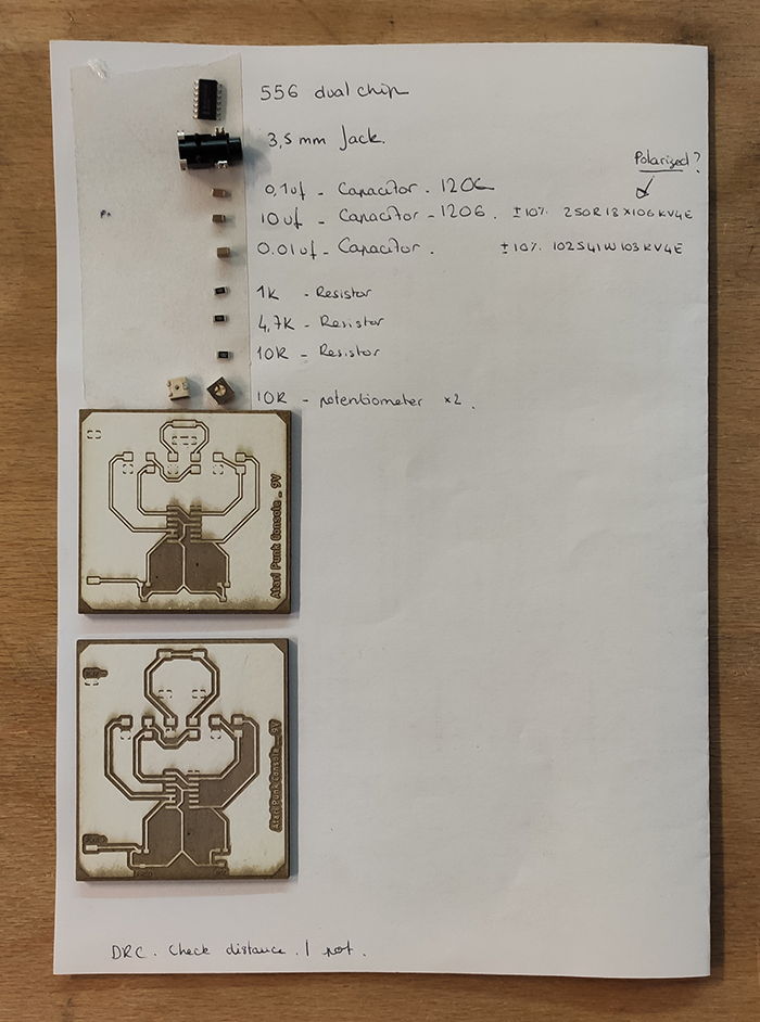
First, I need to gather all the components required in the PCB.
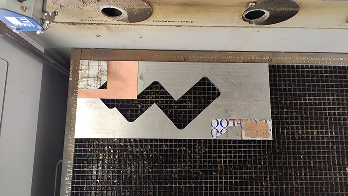
Then I use the laser cutting machine to raster the image of my PCB on cardboard. I could print it on paper to fulfil this purpose, but as I'm in the fablab and the machine is available this is much more exciting.
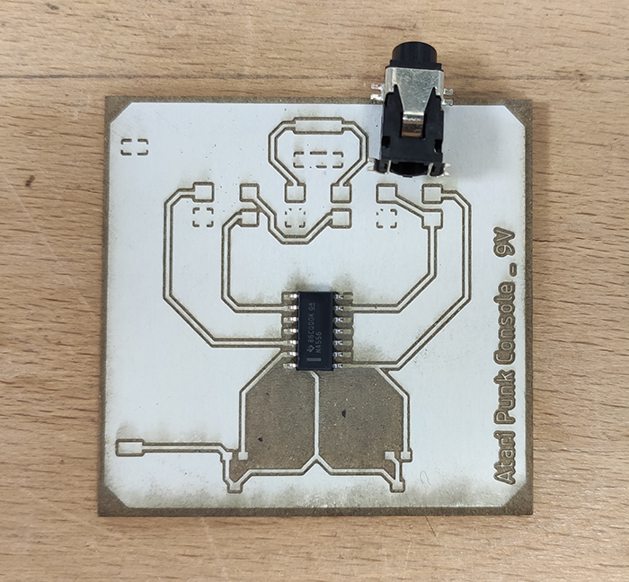
The first result show that the dimensons I used to place the 3.5mm Jack is done wrong and the component can't fit. The traces under the right potentiometer should also be modified to avoid shorts. And the ground may be to close from the traces, I will increase this distance.
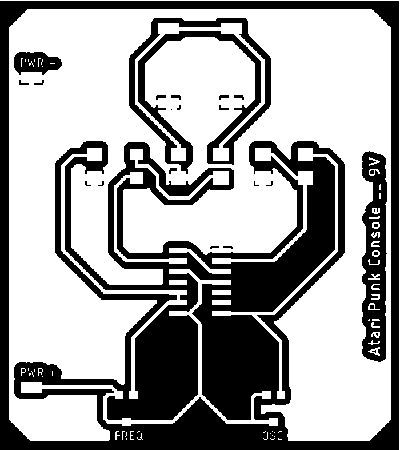
Here is the modified version, that might change again for esthetics purposes.
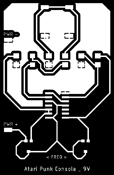
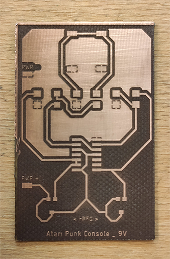
Here is my final version for the APC.
Laser cutting FR4 PCB
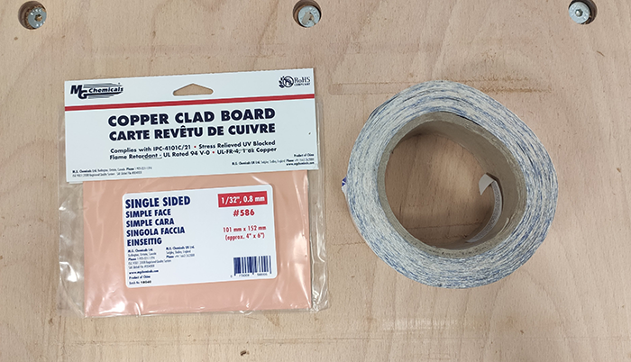
The PCB design and the components are fitting together, we can lasercut the PCB pattern on a FR4 PCB board.
- We're using double-sided tape to maintain our PCB board on a piece of steel.
- We place our pcb on the laser cut machine tray, we can now calibrate the Z axis, then the X and Y. To save our homing we need to push on the directionnal buttin form the laser cut machine interface.
- When our machine is calibrated, we can open Corel Draw to prepare our file. Import and verify the size of the file.
- The laser cut machine behave just like printer for the computer. When our file is imported and correctly sized we can "Print" it (ctrl+p). At this point we have to check if we're using the right "printer", then we can fill the preferences
- As we want to engrave a picture we need to specify our image quality in dpi (1200 in our case).
- We have to choose the laser we're using, we're using the fiber one as we want to engrave a FR4 pcb Board.
- We need to select "raster" instead of vector,
- then we have to specify the power and frequency of the laser regarding the material we're using.
- Verify and "ok" the preference box, then "Apply" the specifications then print.
- The job appears on the laser cutting machine, before sending the job :
- Turn on ventilations !
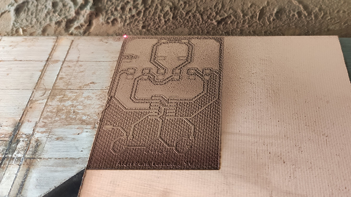
spec : 10/100/1 - Raster Fibre - PCB FR4
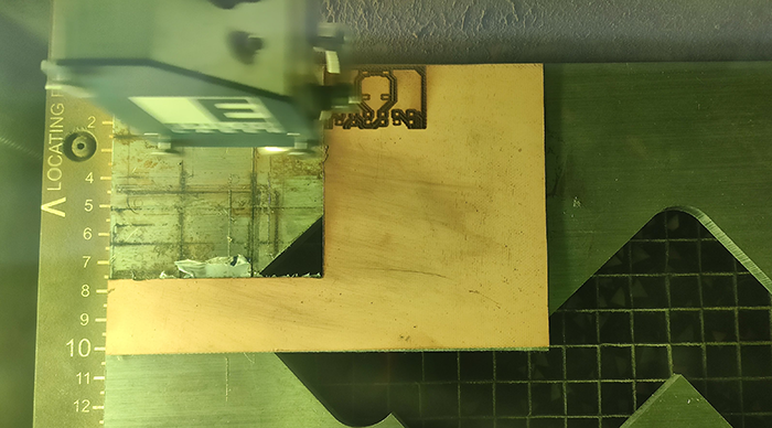
When the job is over, we can use Corel Draw to draw vector lines arounds our pcb image. We have to go through the calibration again since we need to change the laser we're using. We can then prepare and send the job.
The spec. in order to cut around the board : 30/70/100 - Vector C02 - PCB FR4 x 15
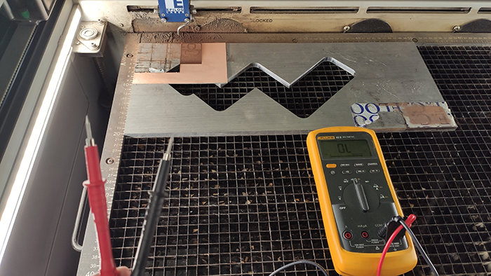
When the job is over we're using the multimeter to check the connections on our board. We want to make sure that there is no short.
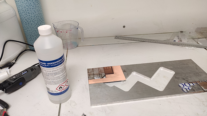
Cleaning the board with Isopropanol : use mask, gloves and glasses. Rub the pcb with a cloth with Isopropanol on it.
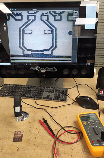
Once the board is cleaned, the last part before soldering is to check our board for shorts a last time, using the microscope to do so.