Designing the Atari Punk Console on Eagle PCB
The Atari Punk Console
Originally designed by Forrest M. Mims III as a "Sound synthetizer", then a "Stepped Tone Generator", and it was renamed the "Atari Punk Console" by Kaustic Machines, as it sounds are similar to the Atari 2600. This famous Lo-Fi synth circuit is using a few components and a 556 dual timer IC (r a pair of 555).
Here is the original Stepped Tone Generator circuit, by Forrest M. Mims III (issued from Mini-Engineer's Notebook - 555 Timer IC Circuits, p.22, published in 1996 by Radio Shack) :
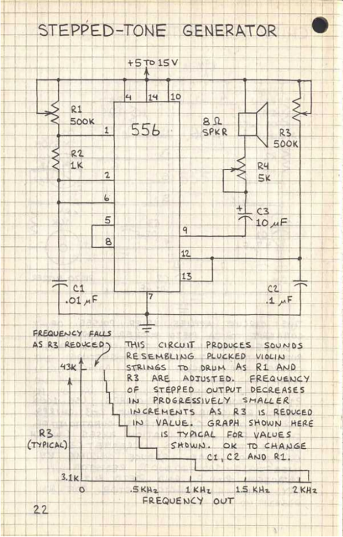
How it works :
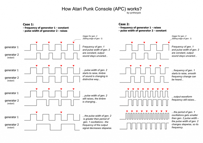
The APC circuit operates a 555 astable circuit, driving a 555 monostable circuit.
"In operation, the first timer is connected as an audio frequency oscillator and the second as a monostable multivibrator. The oscillator drives the monostable, which emits square output pulses with a duration controlled by R3. You have to actually hear the end result to fully appreciate the stepped tones that are generated as R1 and/or R3 are adjusted."
Source : Making music with an Atari Punk Console - Forrest M. Mims III (https://www.jameco.com/Jameco/workshop/diy/atari-punk-console.html)
Here is the APC circuit I made on Falstad, it asccessible here : https://tinyurl.com/y6f2tqtd
Source : https://syntherjack.net/atari-punk-console/
The Atari Punk Console : Eagle PCB Schematics
To reproduce the Atari Punk Console schematics on Eagle PCB, I need to gather all the components required. Firsts issues are : find the components with the right value, according to the circuit, with the right footprint (minimum 1206), to be able to solder them later, and with the right SMD footprint, according to the available components in the fablab.
I met several issues while looking for the required components :
The 556 Chip wasn't with SMD footprints in the libraries I had installed; I had to install the linear library.
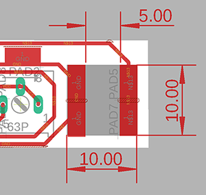
The 3.5 mm jack in my libraries were not with the right footprint. Jonah used SMD Pads with the right size to replicate the footprint :
I couldn't find the trimming potentiometer in the right value
And I couldn't find capacitors in 1206 at first.
So here's an helpful table which gather the parts required and where to find them in the Eagle libraries :
| Quantity | Component | Value | Eagle library | Footprint |
|---|---|---|---|---|
| 1 | 556 dual chip | - | linear | NE556D |
| 2 | Potentiometers | 10K | SparkFun-Resistors | SMD-3MM-CLOSED-1/8 |
| 1 | Resistor | 1K | SparkFun-Resistors | 1206 |
| 1 | Resistor | 4,7K | SparkFun-Resistors | 1206 |
| 1 | Resistor | 10K | SparkFun-Resistors | 1206 |
| 1 | Capacitor | 0.01uf | eagle-ltspice | C1206 |
| 1 | Capacitor | 0.1uf | eagle-ltspice | C1206 |
| 1 | Polarized Capacitor | 10uf | SparkFun-Capacitors | ETA3216-16V-10% |
| 1 | 3.5mm Jack | - | Not found. | Using Pads. |
| 1 | DC Barrel | 9V | Not found. | Using Pads. |
| 1 | Battery | 9V | - | - |
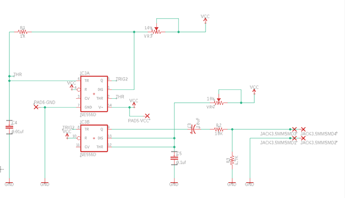
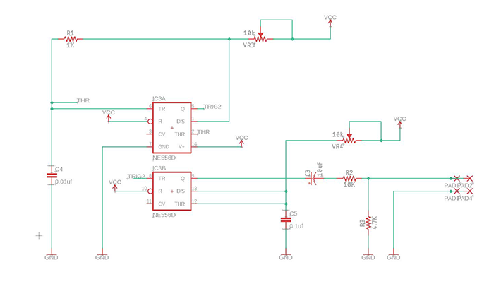
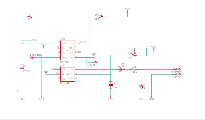
Where I finally gathered all the components the schematics were like this :
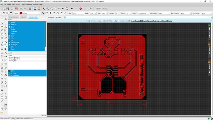
The Atari Punk Console : Eagle PCB Board
The following step was to generate and link all the components on the board following rules :
- Place edge components first (USB ports, Jack, headers)
- Make sure that de decoupling capacitor is close to the IC.
- Don't overlap parts, components need space.
- Traces should not be right-angled.
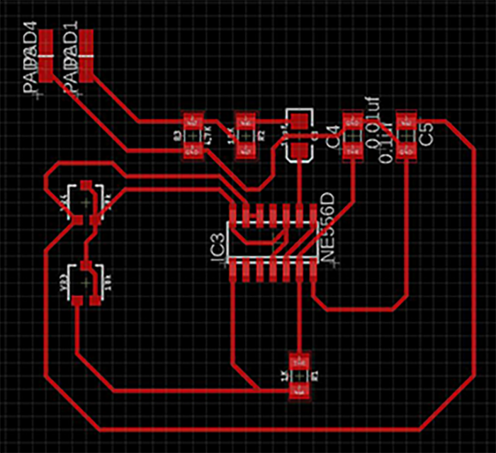
Then my computer was in trouble and decided to shutdown without notice. I didn't save the project so far, so I had to begin again : 2 pads are added on this schematics, to link the battery connector.
DRC Control : Clearance, Distance & Size
Design Rules Check (DRC) checks for :
- Clearance, to avoid signal traces that are too close
- Overlap, to avoid shorts in the circuit
- Dimension, to avoid pads, traces or via to close to the dimension line.
GND Plane & Dimensions
To create the GND plane :
Draw a polygon, name it "GND", then apply Rastness.
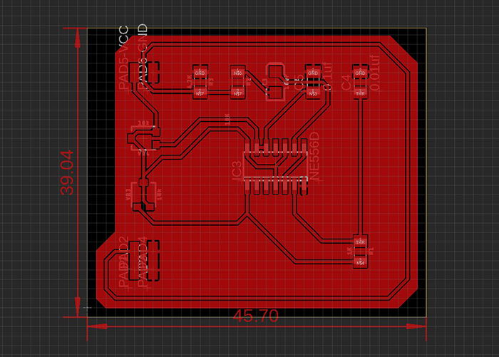
Export & Invert image
Before exporting our board we need to select the layers we need :
TOP
- PADS
DIMENSION
We also need to desactivate the display we don't need :
Options > Set > Misc
Deactivate :
- Display pad names
- Display signal names on pads
Display signal names on traces
Now we can export our board image :
File > Export > image
In the dialog box :
- Set the resolution at 1200 display
Check Monochrome box
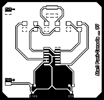
The last part is using Photoshop to invert our image. The lasercutter cuts black.
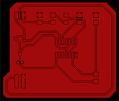
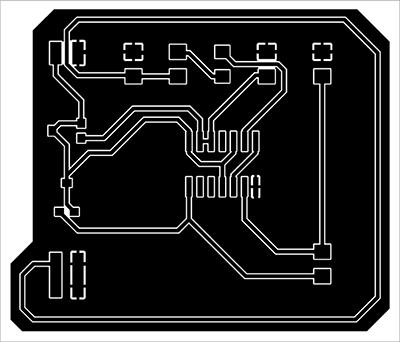
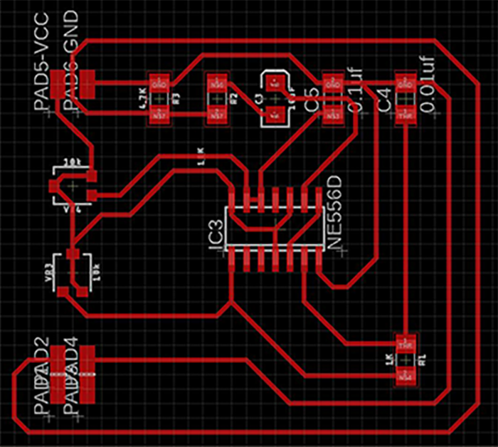
Corrected versions :
The schematics has not change in term of content but in term of display.
Several part of the previous board has been modified :
- Potentiometers are in the same position
- The 3.5mm Jack position
- Orientation of the 556 chip
- Clearance of the GND Plane
- Name of the board and voltage required